TOPOLOGY
INTRODUCTION
This task is based on setting up devices on packet tracer and ensuring there is communication between them
SETTING UP SWITCH, ROUTER AND PCS
REQUIREMENTS
- TWO PCS
- A SWITCH 2960
- A ROUTER 2911
STEP 1 :Building the Topology
Build the topology in Real-time mode in acket tracer Choose the required devices and set them as shown below
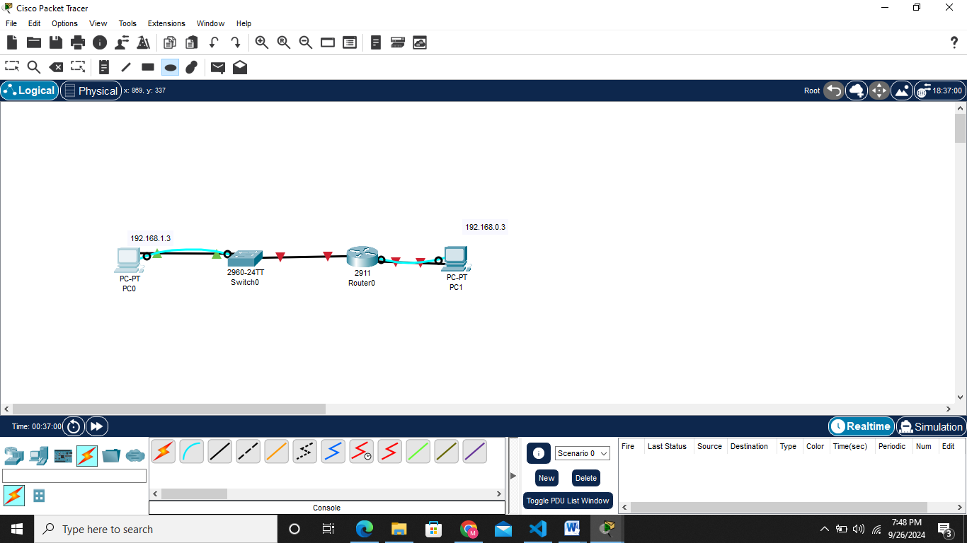
Since the devices are set, i choose to use straight-through cabling since all the devices were different unlike cross-over cabling
NB Routers and pcs used pin 1&2 for transmission and 3&6 as receiving pins.On the other hand switch uses the vice versa of it 3&6 transmitting 1&2 receiving.
STEP 2:Assigning ip address to the devices statically as displayed in the topology table below
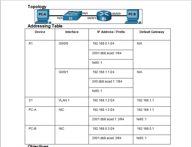 Both ipv4 and ipv6 are set as shown below on PC A
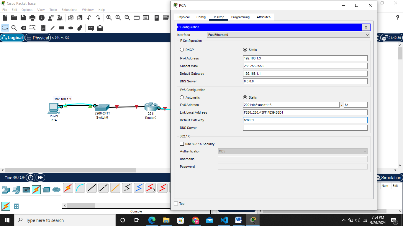
Do the same to PC B 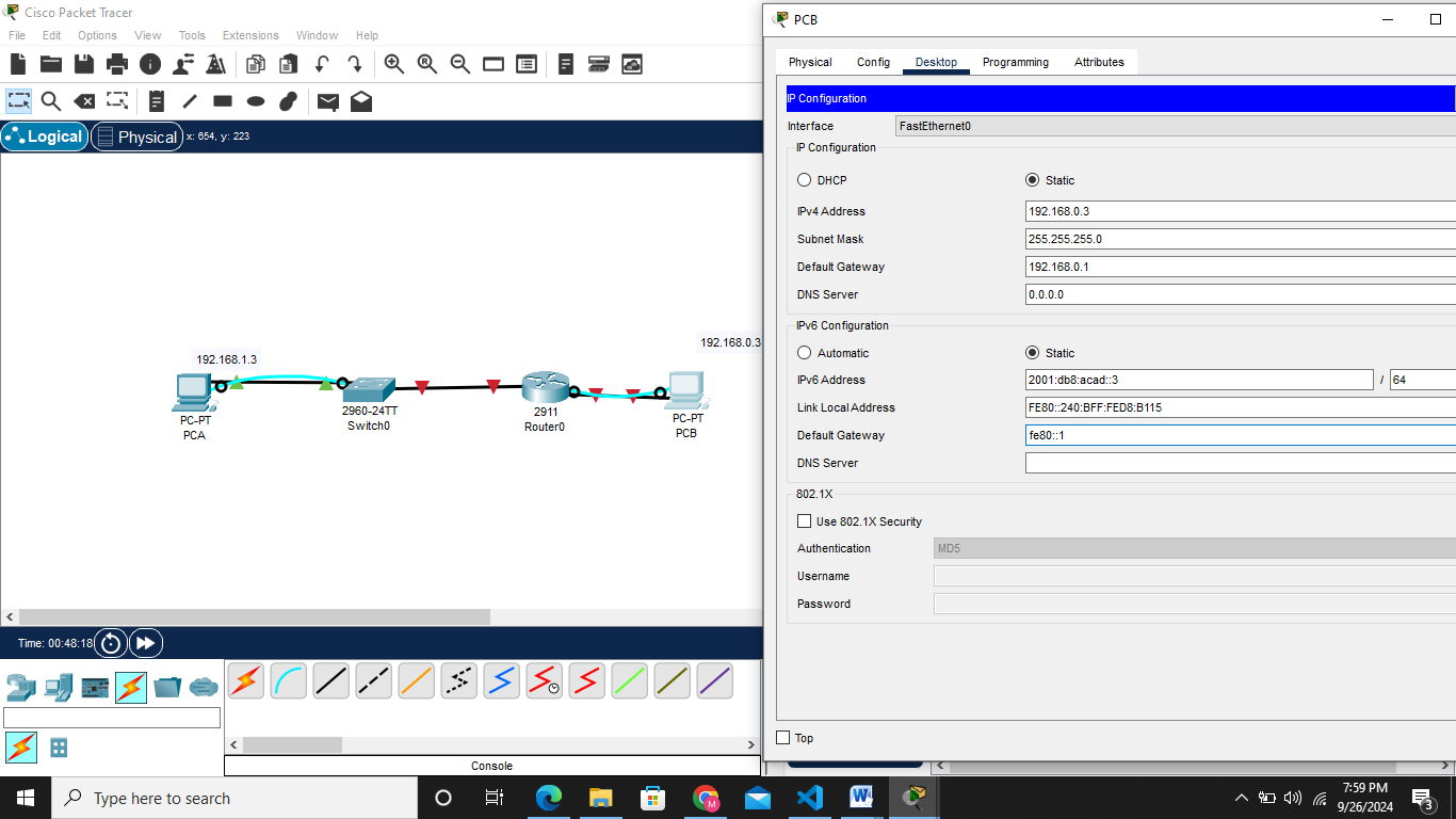
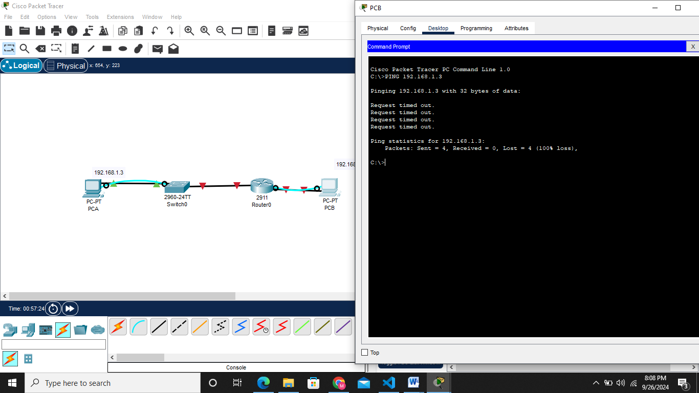
PING THE TWO DEVICES TO CHECK COMMUNICATION
The ping was not succesfull all packets sent were lost
Step 3: Configure the router.
a. Console into the router and enable privileged EXEC mode using Router> enablecommand
b. Enter configuration mode. Router# config terminal
c. Assign a device name to the router. Router(config)# hostname R1
d. Disable DNS lookup to prevent the router from attempting to translate incorrectly entered commands as though they were host names. R1(config)# no ip domain lookup
e. Assign class as the privileged EXEC encrypted password. R1(config)# enable secret class
f. Assign cisco as the console password and enable login.
1
2
3
4
R1(config)# `line console 0`
R1(config-line)# `password cisco`
R1(config-line)# `login`
g. Assign cisco as the VTY password and enable login.
1
2
3
4
R1(config)# `line vty 0 4`
R1(config-line)# `password cisco`
R1(config-line)# `login`
h. Encrypt the plaintext passwords. R1(config)# service password-encryption
i. Create a banner that warns anyone accessing the device that unauthorized access is prohibited. R1(config)# banner motd $ Authorized Users Only! $
j. Configure and activate both interfaces on the router.
1
2
3
4
5
6
7
8
9
10
11
12
R1(config)# `interface GigabitEthernet0/0/0`
R1(config-if)# `ip address 192.168.0.1 255.255.255.0`
R1(config-if)# `ipv6 address 2001:db8:acad::1/64`
R1(config-if)# `ipv6 address FE80::1 link-local`
R1(config-if)# `no shutdown`
R1(config-if)#  `exit`
R1(config)# `interface GigabitEthernet0/0/1`
R1(config-if)# `ip address 192.168.1.1 255.255.255.0`
R1(config-if)# `ipv6 address 2001:db8:acad:1::1/64`
R1(config-if)# `ipv6 address fe80::1 link-local`
R1(config-if)#  `no shutdown`
R1(config-if)#  `exit`
k. Configure an interface description for each interface indicating which device is connected to it
1
2
3
4
5
6
R1(config)#  ` interface GigabitEthernet0/0/1`
R1(config-if)# `description Connected to F0/5 on S1`
R1(config-if)# `exit`
R1(config)# `interface g0/0/0`
R1(config-if)# `description Connected to Host PC-B`
R1(config-if)# `exit`
l. To enable IPv6 routing, enter the command ipv6 unicast-routing. R1(config)# ipv6 unicast-routing
m. Save the running configuration to the startup configuration file.
1
2
3
R1(config)# `exit`
R1# `copy running-config startup-config`
n. Set the clock on the router. R1# clock set 15:30:00 27 Aug 2019